Power NTC Thermistor for Inrush Current Limiting Surge Suppression, ICL, Max. Current 2A, R25 12 Ohm.
ICL Inrush Current Limit NTC Kinked Pin
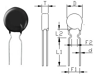
Unit: mm
- Body Diameter D: 13 mm max
- Body Thickness T: 5.5 mm max
- Lead Length L1: 17 mm min
- Lead Length L2: 8±2 mm
- Lead Space F1: 7.5±1 mm
- Lead Space F2: 5±1.5 mm
- Lead Diameter d: 0.8±0.05 mm
Inrush current limiting, e.g. in switch-mode power supplies, soft-start motors
- Resistance at 25C R25: 12 ohm+/-20%
- Max. steady state current: 2A
- Approximate resistance @ max. current: 0.462 ohm
- Thermal Time Constant (in still air): 48 seconds.
- Dissipation Coefficien:14 (mW/C)
- Voltage Proof: AC1500V,1 minute.
- Insulation resistance: DC1000V , 1 minute, ≥500MΩ
- Operating temperature range: -40 — +170C.
- Beta Value (K): 2800 +/-10%
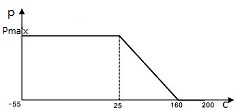
Power NTC Thermistor Load Temperature Characteristics
- Resin coated disk NTC thermistor with uninsulated lead-wires.
- Suitable for both AC and DC circuits up to a voltage of 265 V(rms).
- Excellent mechanical strength.
- Suitable for PCB mounting.
| Test Item | Standard | Test Conditions | Specifications |
|---|---|---|---|
| Lead wire tensile | IEC 60068-2-21 | Test Ua: Force 20N, On 10 Seconds; |
ΔR25/R25 <15%, No visible damage |
| Solderability | IEC 60068-2-20 | 245 ±3℃, 3 ± 0.3 sec | At least 95% of terminal electrode is covered by new solder |
| Resistance to Soldering Heat | IEC 60068-2-20 | 260 ± 3℃, 10 ± 1 sec | ΔR25/R25 <15%, No visible damage |
| Storage in dry heat | IEC 60068-2-2 | Storage at upper category temperature Temperature 170C Time 1000h |
ΔR25/R25 <20%, No visible damage |
| Storage in damp heat, steady state | IEC 60068-2-78 | Temperature of air: 40C Relative humidity of air: 93% Duration: 21 days |
ΔR25/R25 <20%, No visible damage |
| Rapid change of temperature | IEC 60068-2-14 | Lower test temperature: -40C t: 30 min Upper test temperature: 170C t: 30 min Time to change from lower to upper temperature: < 30 s Number of cycles: 10 |
ΔR25/R25 <20%, No visible damage |
| Endurance with max. current |
IEC 60539-1 | Ambient temperature: 25 ±5C I=Imax t: 1000h |
ΔR25/R25 <20%, No visible damage |
| Cyclic endurance | IEC 60539-1 | I=Imax On-time=1 min Cooling time=6 min Number of cycles: 1000 |
ΔR25/R25 <20%, No visible damage |
- For inrush current limiting, the NTC thermistor must be connected in series with the load circuit. Several inrush current limiters can also be connected in series for higher damping.
Inrush current limiters must NOT be connected in parallel. - In general inrush current limiters require time to get back to cold state, in which they can provide adequate inrush current limiting due to their high resistance. The cooling down time depends on ambient conditions.
- It should be considered that the surrounding area of NTC thermistor may become quite hot. Ensure the adjacent components are placed at sufficient distance from a thermistor to allow for proper cooling time of the thermistor.
- Make sure that adjacent materials are designed for operation at temperatures comparable to the surface temperature of the thermistor. Make sure that surrounding parts and materials can withstand this temperature.
- Make sure that thermistor are adequately ventilated to avoid overheating.
- Avoid contamination of the thermistor surface.
- Avoid contact of NTC thermistor with any liquids and solvents. Ensure that no water enters an NTC thermistor.
More information on ICLs NTC Cautions Warnings on Storage Handling Soldering Mounting Operation can be founded in Power NTC Thermistors for Inrush Current Limiting Surge Suppression.
Related AMWEI PTC NTC Thermistors Products for Current Surge Protection

Content Headline
Technical Knowledge
NTC Thermistor Glossary and Definition
How NTC thermistor beta value is calculated?
NTC Thermistor Manufacturing Process and Quality Control
Applications Articles
How to Select NTC Thermistor for Inrush Current Limiting?
NTC thermistor for temperature measurement and control selecting reference information.
Charging Control with AMWEI NTC thermistor
Reliable limiting of current surges by AMWEI NTC and PTC thermistor
How to Select Packaged Thermistor Temperature Sensor Probe Assembly ? 6 Steps


