PTC Thermistor Overcurrent Overload Protection Resettable Fuse

PTC Thermistor Current Protection Resettable Fuse
PTC Thermistor Current Protector Resettable Fuse are ceramic-based doped barium titanate PTC thermistors discs, in through-hole rugged design, used instead of conventional fuses to protect load, such as transformers, instruments, power supply, or electronic circuit, against overcurrent overload and short circuit, for circuit protection inrush current limit function, by utilizing ceramic PTC thermistors thermal property that resistance increases sharply at Curie Temperature (also called Switch Temperature, Reference Temperature), reduces the current flow to the load to an admissible low level.
PTC thermistors protector not only respond to inadmissibly high currents but also if a preset temperature limit is exceeded.
PTC thermistor over-current protector limits the power dissipation of the whole circuit by increasing their resistance and thus reducing the current to a harmless residual value.
In contrast to conventional fuses, PTC thermistor resettable fuses do not have to be replaced after elimination of the fault but resume their protective function immediately after a short cooling-down time.
PTC Thermistor Resistance Change with Current Graph
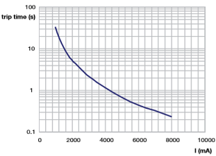
PTC Thermistor Trip Time vs. Current Chart
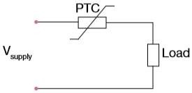
PTC Thermistor as Current Protect Resettable Fuse
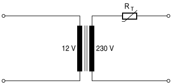
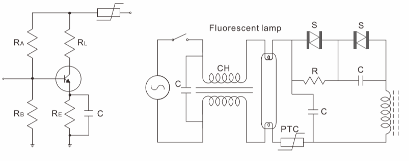
Simplest circuit for PTC Thermistor protecting a transformer
Positive Temperature Coefficient PTC thermistor applies in the over-current overload and short circuit protection of transformers, battery charger, switches, switch power supply, adaptor, meter, instrumentation, apparatus, electronic coils, control panels, air conditioner, automotive electron, etc.
How PTC Thermistor Resettable Fuse Protect Circuit Against Overload Over-current Work? Operating Principle
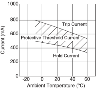
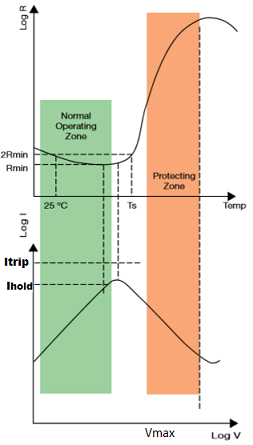
PTC Thermistor Protective Threshold Current Graph
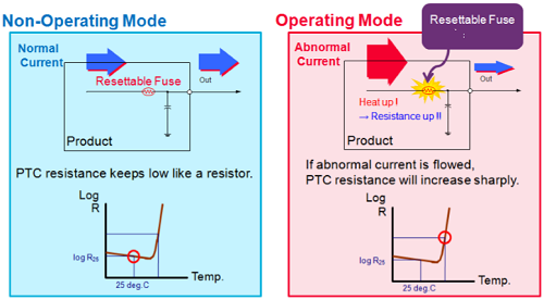
PTC thermistor Resettable Fuse Circuit Protection operating principle is as indicated in the following.
When a circuit is in the normal status, the current through PTC is lower than the rated current and PTC thermistors protector is in the normal state with small resistance value, which will not affect the normal operation of the protected circuit.
In case of some fault in the circuit and the current is greater than the rated current, the PTC thermistor protector will become hot quickly and present a high resistance state, which sets the circuit relatively “off” to protect the circuit from damage.
After the fault is removed, PTC thermistor protector will automatically restore its low resistance state and the circuit will resume normal operation.
Normally, when PTC thermistor is used as an overcurrent protection component, it is preferred to select maximum operating current, maximum operating voltage and proper specifications.
Furthermore such factors should be taken into consideration as the dimensions of the components, rated zero-power resistance, operating temperature range, etc.
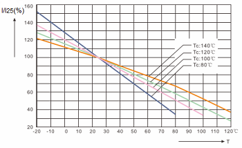
Different Curie Temperature PTC Non-trip Current vs. Ambient Temperature Graph
Relation between operating temperature, operating current and non-operating current is as shown in following Figure. Operating current is normally 2~3 times non-operating current, and both of the currents will be reduced as operating temperature increases.
When connected in series with the input of an electrical or electronic circuit, such as a small motor or power supply, the PTC thermistor acts as a self-resettable fuse, protecting the circuit against current, voltage and temperature overload conditions.
In normal operating conditions the PTC thermistor resistance is low , and the current is below its hold value (Ihold). However, an overload will quickly heat up the PTC thermistor until, at around switch temperature (Ts), its resistance becomes high, limiting the current to far below its trip value (Itrip), and so protecting the circuit.
Operating of PTC Thermistor as Current Protect Resettable Fuse

Benefits
- Protection against overcurrent situations
- Automatic reset from protective trip mode
- Space-saving
- Various characteristics to meet a suitable resistance value
PTC Thermistors for over-current overload protection
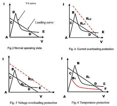
PTC thermistor for current overload protection(Fig. 4):RL1 is the loading current in normal operating state, When overloading resistance decreases, such as transformer short circuit, loading curve changes from RL1to RL2 , exceeding point B, PTC thermistor protector will enter into protection state.
PTC thermistor for voltage overload protection (Fig. 5): Power voltage increases, such as increases abruptly from 220V to 380V, loading curve changes from RL1to RL2 , exceeding point B, PTC thermistor protector will enter into protection state.
More detailed information on AMWEI PTC thermistor for high voltage current surge telecom protection can be founded .
PTC thermistor for temperature protection(Fig. 6): When ambient temperature increases exceeding certain temperature, PTC thermistor voltage-resistance curve changes from A-B-E to A-B1-F, loading curve RL , exceeding point B1, PTC thermistor protector will enter into protection state. More detailed information on AMWEI PTC thermistor for temperature protection can be founded in PTC Thermistors Limit Temperature Sensor Temperature Protection Page.
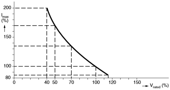
Electrical Characteristics Imax as a Function of Voltage Graph
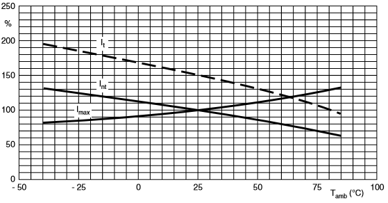
Current Deviation as a Function of Ambient Temperature Chart
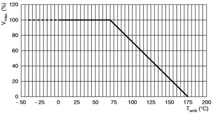
Voltage Derating as a Function of Ambient Temperature Graph
PTC Thermistor Current Protector Application Diagram Examples
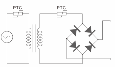
PTC Thermistor Current Protector Transformer Primary or Secondary Protection Diagram
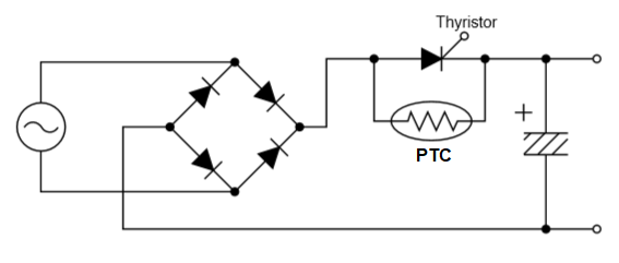
PTC Thermistor for inrush current limit circuit diagram
AMWEI PTC Thermistor Overcurrent Overload Protection Resettable Fuse Engineering Drawing
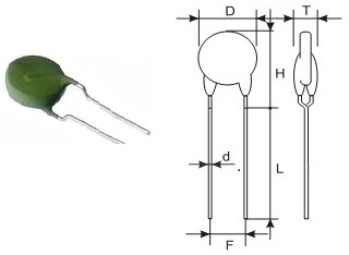
Current Protection PTC Thermistor Outlook Engineering Drawing
| AMWEI Part Number | Resistance at 25C (R25) (Ohm) |
Non-trip Current Int(mA) |
Trip Current @25C It (mA) |
Max. Voltage Vmax (V) |
Max. Current Imax (A) |
Reference Temp Tref |
Dimension (mm) |
|||
|---|---|---|---|---|---|---|---|---|---|---|
| @25C | @60C | Dmax | Tmax | Φd | ||||||
| AMZ11-20P2R6H265 | 2.6 ohm | 650mA | 500mA | 1300mA | 265V | 4.3A | 120C | 22.0 | 5.0 | 0.6 |
| AMZ11-20P3R7H265 | 3.7 ohm | 530mA | 430mA | 1050mA | 265V | 4.3A | 120C | 22.0 | 5.0 | 0.6 |
| AMZ11-20P5RH265 | 5.0 ohm | 480mA | 370mA | 970mA | 265V | 4.3A | 120C | 22.0 | 5.0 | 0.6 |
| AMZ11-16P5RH265 | 5.0 ohm | 420mA | 320mA | 840mA | 265V | 3.1A | 120C | 17.5 | 5.0 | 0.6 |
| AMZ11-16P6RH265 | 6.0 ohm | 390mA | 300mA | 780mA | 265V | 3.1A | 120C | 17.5 | 5.0 | 0.6 |
| AMZ11-16P7RH265 | 7.0 ohm | 350mA | 280mA | 700mA | 265V | 3.1A | 120C | 17.5 | 5.0 | 0.6 |
| AMZ11-13P10RH265 | 10 ohm | 260mA | 200mA | 520mA | 265V | 1.8A | 120C | 14.0 | 5.0 | 0.6 |
| AMZ11-13P12RH265 | 12 ohm | 225mA | 180mA | 450mA | 265V | 1.8A | 120C | 14.0 | 5.0 | 0.6 |
| AMZ11-13P50RH265 | 50 ohm | 130mA | 100mA | 260mA | 265V | 1.8A | 120C | 14.0 | 5.0 | 0.6 |
| AMZ11-12P7RH265 | 7 ohm | 320mA | 250mA | 640mA | 265V | 1.8A | 120C | 14.0 | 5.5 | 0.6 |
| AMZ11-12P8RH265 | 8 ohm | 300mA | 230mA | 600mA | 265V | 1.8A | 120C | 14.0 | 5.5 | 0.6 |
| AMZ11-12P9RH265 | 9 ohm | 290mA | 220mA | 580mA | 265V | 1.8A | 120C | 14.0 | 5.5 | 0.6 |
| AMZ11-12P10RH265 | 10 ohm | 250mA | 200mA | 500mA | 265V | 1.8A | 120C | 14.0 | 5.5 | 0.6 |
| AMZ11-12P12RH265 | 12 ohm | 240mA | 180mA | 480mA | 265V | 1.8A | 120C | 14.0 | 5.5 | 0.6 |
| AMZ11-12P15RH265 | 15 ohm | 200mA | 160mA | 400mA | 265V | 1.8A | 120C | 14.0 | 5.5 | 0.6 |
| AMZ11-12P27RH270 | 27 ohm | 120mA | 90mA | 350mA | 270V | 1.8A | 120C | 14.0 | 5.5 | 0.6 |
| AMZ11-12P101N265 | 100 ohm | 50mA | 40mA | 100mA | 265V | 1.8A | 120C | 14.0 | 5.5 | 0.6 |
| AMZ11-10P12RH265 | 12 ohm | 230mA | 160mA | 460mA | 265V | 1.2A | 120C | 11.5 | 5.0 | 0.6 |
| AMZ11-10P15RH265 | 15 ohm | 180mA | 140mA | 350mA | 265V | 1.2A | 120C | 11.5 | 5.0 | 0.6 |
| AMZ11-10P18RH265 | 18 ohm | 170mA | 130mA | 340mA | 265V | 1.2A | 120C | 11.5 | 5.0 | 0.6 |
| AMZ11-10P39RH265 | 39 ohm | 130mA | 100mA | 250mA | 265V | 1.2A | 120C | 11.5 | 5.0 | 0.6 |
| AMZ11-08P15RH250 | 15 ohm | 150mA | 120mA | 300mA | 250V | 0.8A | 120C | 9.5 | 5.0 | 0.6 |
| AMZ11-08P22RH250 | 22 ohm | 135mA | 110mA | 270mA | 250V | 0.8A | 120C | 9.5 | 5.0 | 0.6 |
| AMZ11-08P25RH265 | 25 ohm | 130mA | 100mA | 250mA | 265V | 0.8A | 120C | 9.5 | 5.0 | 0.6 |
| AMZ11-08P35RH265 | 35 ohm | 115mA | 90mA | 225mA | 265V | 0.8A | 120C | 9.5 | 5.0 | 0.6 |
| AMZ11-08P39RH270 | 39 ohm | 105mA | 70mA | 210mA | 270V | 0.8A | 120C | 9.5 | 5.0 | 0.6 |
| AMZ11-08P45RH265 | 45 ohm | 105mA | 80mA | 200mA | 265V | 0.8A | 120C | 9.5 | 5.0 | 0.6 |
| AMZ11-08P55RH265 | 55 ohm | 90mA | 70mA | 180mA | 265V | 0.8A | 120C | 9.5 | 5.0 | 0.6 |
| AMZ11-08P70RH265 | 70 ohm | 75mA | 60mA | 150mA | 265V | 0.8A | 120C | 9.5 | 5.0 | 0.6 |
| AMZ11-07P82RH265 | 82 ohm | 70mA | 50mA | 140mA | 265V | 0.6A | 120C | 8.5 | 5.0 | 0.6 |
| AMZ11-07P56RH265 | 56 ohm | 90mA | 60mA | 175mA | 265V | 0.6A | 120C | 8.5 | 5.0 | 0.6 |
| AMZ11-06P33RH250 | 33 ohm | 110mA | 85mA | 200mA | 250V | 0.4A | 120C | 7.5 | 4.5 | 0.6 |
| AMZ11-05P70RH265 | 70 ohm | 65mA | 50mA | 130mA | 265V | 0.3A | 120C | 6.5 | 5.0 | 0.6 |
| AMZ11-05P85RH265 | 85 ohm | 60mA | 45mA | 120mA | 265V | 0.3A | 120C | 6.5 | 5.0 | 0.6 |
| AMZ11-05P121H265 | 120 ohm | 45mA | 35mA | 90mA | 265V | 0.3A | 120C | 6.5 | 5.0 | 0.6 |
| AMZ11-05P181H265 | 180 ohm | 40mA | 30mA | 80mA | 265V | 0.3A | 120C | 6.5 | 5.0 | 0.6 |
| AMZ11-04P70RH250 | 70 ohm | 50mA | 40mA | 100mA | 250V | 0.2A | 120C | 5.5 | 5.0 | 0.6 |
| AMZ11-04P121H265 | 120 ohm | 40mA | 30mA | 80mA | 265V | 0.2A | 120C | 5.5 | 5.0 | 0.6 |
| AMZ11-03P151H250 | 150 ohm | 40mA | 30mA | 75mA | 250V | 0.2A | 120C | 4.5 | 5.0 | 0.5 |
| AMZ11-03P221H265 | 220 ohm | 30mA | 24mA | 60mA | 265V | 0.2A | 120C | 4.5 | 5.0 | 0.5 |
| AMZ11-12N12RH265 | 12 ohm | 200mA | 140mA | 400mA | 265V | 1.8A | 100C | 14.0 | 5.0 | 0.6 |
| AMZ11-12N10RH265 | 10 ohm | 220mA | 180mA | 440mA | 265V | 1.8A | 100C | 14.0 | 5.0 | 0.6 |
| AMZ11-12N8RH265 | 8 ohm | 250mA | 200mA | 500mA | 265V | 1.8A | 100C | 14.0 | 5.0 | 0.6 |
| AMZ11-10N12RH250 | 12 ohm | 180mA | 130mA | 350mA | 250V | 1.2A | 100C | 11.5 | 5.0 | 0.6 |
| AMZ11-10N12RH265 | 12 ohm | 210mA | 160mA | 420mA | 265V | 1.2A | 100C | 12.0 | 5.0 | 0.6 |
| AMZ11-10N15RH265 | 15 ohm | 175mA | 120mA | 320mA | 265V | 1.2A | 100C | 11.5 | 5.0 | 0.6 |
| AMZ11-10N18RH265 | 18 ohm | 145mA | 110mA | 320mA | 265V | 1.2A | 100C | 11.5 | 5.0 | 0.6 |
| AMZ11-10N22RH265 | 22 ohm | 140mA | 100mA | 260mA | 265V | 1.2A | 100C | 11.5 | 5.0 | 0.6 |
| AMZ11-10N27RH265 | 27 ohm | 120mA | 90mA | 240mA | 265V | 1.2A | 100C | 11.5 | 5.0 | 0.6 |
| AMZ11-08N25RH265 | 25 ohm | 110mA | 80mA | 230mA | 265V | 1.0A | 100C | 9.5 | 5.0 | 0.6 |
| AMZ11-08N35RH265 | 35 ohm | 95mA | 70mA | 190mA | 265V | 1.0A | 100C | 9.5 | 5.0 | 0.6 |
| AMZ11-08N45RH265 | 45 ohm | 85mA | 55mA | 170mA | 265V | 1.0A | 100C | 9.5 | 5.0 | 0.6 |
| AMZ11-07N22RH250 | 22 ohm | 120mA | 80mA | 210mA | 250V | 0.5A | 100C | 8.5 | 5.0 | 0.6 |
| AMZ11-07N35RH265 | 35 ohm | 95mA | 70mA | 190mA | 265V | 0.5A | 100C | 8.5 | 5.0 | 0.6 |
| AMZ11-07N50RH265 | 50 ohm | 85mA | 60mA | 170mA | 265V | 0.5A | 100C | 8.5 | 5.0 | 0.6 |
| AMZ11-07N60RH265 | 60 ohm | 80mA | 50mA | 160mA | 265V | 0.5A | 100C | 8.5 | 5.0 | 0.6 |
| AMZ11-05N82RH265 | 82 ohm | 55mA | 40mA | 105mA | 265V | 0.3A | 100C | 6.5 | 5.0 | 0.6 |
| AMZ11-05N101H265 | 100 ohm | 50mA | 35mA | 100mA | 265V | 0.3A | 100C | 6.5 | 5.0 | 0.6 |
| AMZ11-05N121H265 | 120 ohm | 45mA | 32mA | 90mA | 265V | 0.3A | 100C | 6.5 | 5.0 | 0.6 |
| AMZ11-05N151H265 | 150 ohm | 38mA | 30mA | 80mA | 265V | 0.3A | 100C | 6.5 | 5.0 | 0.6 |
| AMZ11-05N201H265 | 200 ohm | 30mA | 25mA | 65mA | 265V | 0.3A | 100C | 6.5 | 5.0 | 0.6 |
| AMZ11-05N301H265 | 300 ohm | 27mA | 20mA | 55mA | 265V | 0.3A | 100C | 6.5 | 5.0 | 0.6 |
| AMZ11-05N601H265 | 600 ohm | 20mA | 12mA | 40mA | 265V | 0.2A | 100C | 6.5 | 5.0 | 0.6 |
| AMZ11-04N151H265 | 150 ohm | 36mA | 28mA | 80mA | 265V | 0.3A | 100C | 5.5 | 5.0 | 0.6 |
| AMZ11-03N151H265 | 150 ohm | 33mA | 25mA | 65mA | 265V | 0.2A | 100C | 4.5 | 5.0 | 0.5 |
| AMZ11-03N101H250 | 100 ohm | 40mA | 30mA | 80mA | 250V | 0.2A | 100C | 4.5 | 5.0 | 0.5 |
| AMZ11-03N70RH250 | 70 ohm | 45mA | 35mA | 90mA | 250V | 0.1A | 100C | 4.5 | 5.0 | 0.5 |
| AMZ11-08M25RH265 | 25 ohm | 90mA | 50mA | 180mA | 265V | 0.8A | 80C | 9.5 | 5.0 | 0.6 |
| AMZ11-08M35RH265 | 35 ohm | 80mA | 45mA | 160mA | 265V | 0.8A | 80C | 9.5 | 5.0 | 0.6 |
| AMZ11-08M40RH265 | 40 ohm | 75mA | 40mA | 150mA | 265V | 0.8A | 80C | 9.5 | 5.0 | 0.6 |
| AMZ11-08M50RH265 | 50 ohm | 60mA | 35mA | 120mA | 265V | 0.8A | 80C | 9.5 | 5.0 | 0.6 |
| AMZ11-07M101H265 | 100 ohm | 40mA | 25mA | 80mA | 265V | 0.6A | 80C | 8.5 | 5.0 | 0.6 |
| AMZ11-05M70RH250 | 70 ohm | 50mA | 30mA | 100mA | 250V | 0.3A | 80C | 6.5 | 5.0 | 0.6 |
| AMZ11-05M121H265 | 120 ohm | 30mA | 20mA | 60mA | 265V | 0.3A | 80C | 6.5 | 5.0 | 0.6 |
| AMZ11-03M101H250 | 100 ohm | 25mA | 18mA | 55mA | 250V | 0.2A | 80C | 4.5 | 5.0 | 0.5 |
| AMZ11-03M151H265 | 150 ohm | 22mA | 15mA | 45mA | 265V | 0.2A | 80C | 4.5 | 5.0 | 0.5 |
| AMWEI Part Number | Resistance @25C (R25) (Ohm) |
Non-trip Current Int(mA) |
Trip Current @25C It (mA) |
Max. Voltage Vmax (V) |
Max. Current Imax (A) |
Reference Temp Tref |
Dimension (mm) |
|||
|---|---|---|---|---|---|---|---|---|---|---|
| @25C | @60C | Dmax | Tmax | Φd | ||||||
| AMZ12-20P1R5H140 | 1.5 ohm | 850mA | 680mA | 1700mA | 140V | 4.3A | 120C | 22.0 | 5.0 | 0.6 |
| AMZ12-20P2R6H140 | 2.6 ohm | 650mA | 500mA | 1300mA | 140V | 4.3A | 120C | 22.0 | 5.0 | 0.6 |
| AMZ12-16P4R7H140 | 4.7 ohm | 425mA | 330mA | 850mA | 140V | 3.1A | 120C | 17.5 | 5.0 | 0.6 |
| AMZ12-16P5R6H140 | 5.6 ohm | 400mA | 310mA | 800mA | 140V | 3.1A | 120C | 17.5 | 5.0 | 0.6 |
| AMZ12-13P6R8H140 | 6.8 ohm | 325mA | 250mA | 650mA | 140V | 1.8A | 120C | 14.0 | 5.0 | 0.6 |
| AMZ12-12P5R6H140 | 5.6 ohm | 325mA | 250mA | 650mA | 140V | 1.8A | 120C | 13.5 | 5.0 | 0.6 |
| AMZ12-12P6R8H140 | 6.8 ohm | 300mA | 230mA | 600mA | 140V | 1.8A | 120C | 13.5 | 5.0 | 0.6 |
| AMZ12-10P10RH140 | 10 ohm | 225mA | 170mA | 450mA | 140V | 1.2A | 120C | 11.5 | 5.0 | 0.6 |
| AMZ12-10P6R8H140 | 6.8 ohm | 275mA | 200mA | 550mA | 140V | 1.2A | 120C | 11.5 | 5.0 | 0.6 |
| AMZ12-08P22RH140 | 22 ohm | 135mA | 110mA | 270mA | 140V | 0.8A | 120C | 9.5 | 5.0 | 0.6 |
| AMZ12-06P25RH140 | 25 ohm | 125mA | 90mA | 250mA | 140V | 0.5A | 120C | 7.0 | 5.0 | 0.6 |
| AMZ12-16R2RIH140 | 2.1 ohm | 710mA | 570mA | 1420mA | 140V | 3.1A | 140C | 17.5 | 5.0 | 0.6 |
| AMZ12-13R3R8H140 | 3.8 ohm | 500mA | 400mA | 1000mA | 140V | 1.8A | 140C | 14.5 | 5.0 | 0.6 |
| AMZ12-10R15RH140 | 15 ohm | 210mA | 170mA | 420mA | 140V | 1.2A | 140C | 11.5 | 5.0 | 0.6 |
| AMZ12-10R6R7H140 | 6.7 ohm | 300mA | 230mA | 600mA | 140V | 1.2A | 140C | 11.5 | 5.0 | 0.6 |
| AMZ12-10R10RH140 | 10 ohm | 250mA | 200mA | 500mA | 140V | 1.2A | 140C | 11.5 | 5.0 | 0.6 |
| AMZ12-08R12RH140 | 12 ohm | 200mA | 160mA | 400mA | 140V | 0.6A | 140C | 9.5 | 5.0 | 0.6 |
| AMWEI Part Number | Resistance @25C (R25) (Ohm) |
Non-trip Current Int(mA) |
Trip Current @25C It (mA) |
Max. Voltage Vmax (V) |
Max. Current Imax (A) |
Reference Temp Tref |
Dimension (mm) |
|||
|---|---|---|---|---|---|---|---|---|---|---|
| @25C | @60C | Dmax | Tmax | Φd | ||||||
| AMZ13-16P2R3H60 | 2.3 ohm | 550mA | 450mA | 1100mA | 60V | 8.0A | 120C | 17.5 | 4.0 | 0.6 |
| AMZ13-12P3R7H60 | 3.7 ohm | 380mA | 320mA | 750mA | 60V | 5.5A | 13.5 | 4.0 | 0.6 | |
| AMZ13-10P5R6H60 | 5.6 ohm | 300mA | 250mA | 600mA | 60V | 4.3A | 11.0 | 4.0 | 0.6 | |
| AMZ13-08P9R4H60 | 9.4 ohm | 180mA | 150mA | 360mA | 60V | 3.0A | 9.0 | 4.0 | 0.6 | |
| AMZ13-05P25RH60 | 25 ohm | 100mA | 85mA | 200mA | 60V | 1.0A | 6.5 | 4.0 | 0.6 | |
| AMZ13-03P55RH60 | 55 ohm | 60mA | 50mA | 120mA | 60V | 0.7A | 4.5 | 4.0 | 0.5 | |
| AMZ13-08M4R7H60 | 4.7 ohm | 180mA | 120mA | 360mA | 60V | 3.0A | 80C | 9.0 | 4.0 | 0.6 |
AMWEI PTC thermistor Current Limiting Devices for Transformer Over-current Overload Protection 265V, 100C
(For application of PTC thermistor protector installation inside transformer windings coil)
(For application of PTC thermistor protector installation inside transformer windings coil)
| AMWEI Part Number | Resistance @25C (R25) (Ohm) |
Non-trip Current Int(mA) |
Trip Current @25C It (mA) |
Max. Voltage Vmax (V) |
Max. Current Imax (A) |
Reference Temp Tref |
Dimension (mm) |
|||
|---|---|---|---|---|---|---|---|---|---|---|
| @25C | @80C | Dmax | Tmax | Φd | ||||||
| AMZ11-05N121H265 | 120 ohm | 45mA | 25mA | 90mA | 265V | 0.4A | 100C | 6.5 | 5.0 | 0.6 |
| AMZ11-05N151H265 | 150 ohm | 38mA | 20mA | 80mA | 265V | 0.4A | 6.5 | 5.0 | 0.6 | |
| AMZ11-07N22RH265 | 22 ohm | 110mA | 60mA | 220mA | 265V | 0.7A | 8.0 | 4.5 | 0.6 | |
| AMZ11-07N32RH265 | 32 ohm | 95mA | 50mA | 190mA | 265V | 0.7A | 8.0 | 4.5 | 0.6 | |
| AMZ11-07N55RH265 | 55 ohm | 70mA | 40mA | 140mA | 265V | 0.7A | 8.0 | 5.0 | 0.6 | |
| AMZ11-08N30RH265 | 30 ohm | 100mA | 55mA | 200mA | 265V | 1.0A | 9.0 | 5.0 | 0.6 | |
| AMZ11-08N35RH265 | 35 ohm | 90mA | 50mA | 180mA | 265V | 1.0A | 9.0 | 5.0 | 0.6 | |
| AMZ11-08N40RH265 | 40 ohm | 85mA | 45mA | 170mA | 265V | 1.0A | 9.0 | 5.0 | 0.6 | |
| AMZ11-08N39RH265 | 39 ohm | 95mA | 50mA | 180mA | 265V | 1.2A | 9.5 | 5.0 | 0.6 | |
| AMZ11-08N25RH265 | 25 ohm | 110mA | 60mA | 220mA | 265V | 1.2A | 9.5 | 5.0 | 0.6 | |
| AMZ11-10N22RH265 | 22 ohm | 125mA | 70mA | 250mA | 265V | 1.5A | 11.0 | 5.0 | 0.6 | |
| AMZ11-10N18RH265 | 18 ohm | 145mA | 80mA | 290mA | 265V | 1.5A | 11.0 | 5.0 | 0.6 | |
| AMZ11-10N12RH265 | 12 ohm | 170mA | 95mA | 340mA | 265V | 1.5A | 11.0 | 5.0 | 0.6 | |
| AMZ11-12N18RH265 | 18 ohm | 180mA | 100mA | 360mA | 265V | 2.0A | 13.5 | 5.0 | 0.6 | |
| AMZ11-12N12RH265 | 12 ohm | 210mA | 120mA | 420mA | 265V | 2.0A | 13.5 | 5.0 | 0.6 | |
Note: If not specified, Resistance @25C (R25) tolerance shall be +/-25%.
AMWEI PTC Thermistor Current Limiting Devices for Transformer over-current Overload Protection 265V 120C
(For application of PTC thermistor protector installation outside transformer windings coil)
(For application of PTC thermistor protector installation outside transformer windings coil)
| AMWEI Part Number | Resistance @25C (R25) (Ohm) |
Non-trip Current Int(mA) |
Trip Current @25C It (mA) |
Max. Voltage Vmax (V) |
Max. Current Imax (A) |
Reference Temp Tref |
Dimension (mm) |
|||
|---|---|---|---|---|---|---|---|---|---|---|
| @25C | @60C | Dmax | Tmax | Φd | ||||||
| AMZ11-16P6RH265 | 6.0 ohm | 390mA | 300mA | 780mA | 265V | 3.1A | 120C | 17.5 | 5.0 | 0.6 |
| AMZ11-13P10RH265 | 10 ohm | 260mA | 200mA | 520mA | 265V | 1.8A | 14.0 | 5.0 | 0.6 | |
| AMZ11-12P10RH265 | 10 ohm | 250mA | 200mA | 500mA | 265V | 1.8A | 13.5 | 5.0 | 0.6 | |
| AMZ11-10P15RH265 | 15 ohm | 180mA | 140mA | 350mA | 265V | 1.2A | 11.0 | 5.0 | 0.6 | |
| AMZ11-08P25RH265 | 25 ohm | 130mA | 100mA | 250mA | 265V | 0.8A | 9.0 | 5.0 | 0.6 | |
| AMZ11-08P35RH265 | 35 ohm | 115mA | 90mA | 225mA | 265V | 0.8A | 9.0 | 5.0 | 0.6 | |
| AMZ11-08P45RH265 | 45 ohm | 105mA | 80mA | 200mA | 265V | 0.8A | 9.0 | 5.0 | 0.6 | |
| AMZ11-08P55RH265 | 55 ohm | 90mA | 70mA | 180mA | 265V | 0.8A | 9.0 | 5.0 | 0.6 | |
| AMZ11-05P70RH265 | 70 ohm | 65mA | 50mA | 130mA | 265V | 0.3A | 6.5 | 5.0 | 0.6 | |
| AMZ11-03P151H250 | 150 ohm | 40mA | 30mA | 75mA | 250V | 0.2A | 4.5 | 5.0 | 0.5 | |
Note: If not specified, Resistance @25C (R25) tolerance shall be +/-25%.
AMWEI PTC thermistor current limiting devices for measuring instrumentation and meter circuit overload and short circuit protection, Voltage 265V/420V/550V, Reference Temperature 80C, 100C, 120C
| AMWEI Part Number | Resistance @25C (R25) (Ohm) |
Non-trip Current Int(mA) |
Trip Current @25C It (mA) |
Max. Voltage Vmax (V) |
Max. Current Imax (A) |
Reference Temp Tref |
Dimension (mm) |
|||
|---|---|---|---|---|---|---|---|---|---|---|
| @25C | @60C | Dmax | Tmax | Φd | ||||||
| AMZ11-03M151N265 | 150 ohm | 20mA | 15mA | 50mA | 265V | 0.2A | 80C | 4.5 | 5.0 | 0.5 |
| AMZ11-03M102N265 | 1000 ohm | 10mA | 7mA | 20mA | 265V | 0.1A | 4.5 | 5.0 | 0.5 | |
| AMZ11-03M152N265 | 1500 ohm | 7mA | 5mA | 15mA | 265V | 0.1A | 4.5 | 5.0 | 0.5 | |
| AMZ11-04M45RN265 | 45 ohm | 40mA | 30mA | 80mA | 265V | 0.3A | 5.5 | 5.0 | 0.6 | |
| AMZ11-05M601N420 | 600 ohm | 20mA | 16mA | 40mA | 420V | 0.2A | 6.5 | 5.0 | 0.6 | |
| AMZ11-05M232N420 | 2300 ohm | 8mA | 6mA | 17mA | 420V | 0.1A | 6.5 | 5.0 | 0.6 | |
| AMZ11-05M312N420 | 3100 ohm | 5mA | 4mA | 13mA | 420V | 0.1A | 6.5 | 5.0 | 0.6 | |
| AMZ11-07M251N265 | 250 ohm | 25mA | 20mA | 50mA | 265V | 0.5A | 8.0 | 5.0 | 0.6 | |
| AMZ11-07M112M550 | 1100 ohm | 15mA | 10mA | 30mA | 550V | 0.5A | 8.0 | 7.0 | 0.6 | |
| AMZ11-08M12RN265 | 12 ohm | 120mA | 70mA | 220mA | 265V | 0.8A | 9.0 | 5.0 | 0.6 | |
| AMZ11-03N151N265 | 150 ohm | 30mA | 25mA | 60mA | 265V | 0.2A | 100C | 4.5 | 5.0 | 0.5 |
| AMZ11-03N401N265 | 400 ohm | 25mA | 20mA | 45mA | 265V | 0.2A | 4.5 | 5.0 | 0.5 | |
| AMZ11-05N751N420 | 750 ohm | 25mA | 20mA | 45mA | 420V | 0.2A | 6.5 | 5.0 | 0.6 | |
| AMZ11-05P39RN265 | 39 ohm | 85mA | 70mA | 170mA | 265V | 0.4A | 120C | 6.5 | 5.0 | 0.6 |
| AMZ11-05P65RN265 | 65 ohm | 70mA | 60mA | 140mA | 265V | 0.4A | 6.5 | 5.0 | 0.6 | |
| AMZ11-05P601N420 | 600 ohm | 20mA | 16mA | 39mA | 420V | 0.2A | 6.5 | 5.0 | 0.6 | |
| AMZ11-05P122N550 | 1200 ohm | 15mA | 10mA | 30mA | 550V | 0.1A | 6.5 | 5.0 | 0.6 | |
| AMZ11-05P152N550 | 1500 ohm | 12mA | 7mA | 24mA | 550V | 0.1A | 6.5 | 5.0 | 0.6 | |
| AMZ11A-08P70RN420 | 70 ohm | 64mA | 50mA | 127mA | 420V | 1.4A | 8.5 | 7.0 | 0.6 | |
| AMZ11A-08P121N420 | 120 ohm | 49mA | 40mA | 97mA | 420V | 1.4A | 8.5 | 7.0 | 0.6 | |
| AMZ11A-08P151N420 | 150 ohm | 43mA | 35mA | 86mA | 420V | 1.4A | 8.5 | 7.0 | 0.6 | |
| AMZ11A-08P501N550 | 500 ohm | 24mA | 19mA | 48mA | 550V | 1.0A | 8.5 | 7.0 | 0.6 | |
Note: If not specified, Resistance @25C (R25) tolerance shall be +/-30%.
| Test Item | Standard | Test conditions | |ΔR25/R25| |
|---|---|---|---|
| Switching test at room temperature | IEC 60738-1 | Imax, Vmax, 50 cycles. | <25% |
| Rapid change of temperature in air | IEC600628-2-14, Test Na |
T=TLCT, T=TUCT 5 cycles, 30minutes. |
<10% |
| Endurance at max. operating temperature and max. operating voltage |
IEC 60738-1 | Ambient temperature: +60℃, Maximum Operating Voltage, Current limited to Imax. Time: 24 hours |
<25% |
| Storage in damp heat | IEC 600628-2-3 | Temperature of air: 40℃, Relative humidity of air: 93%, Duration: 56 days |
<10% |
| Lead wire tensile | IEC60068-2-21 | Test Ua: pull strength 10N, 10 seconds, Test Ub: bending 90°, pull strength 5N, successively twice. Test Uc: revolving 180°, successively twice. |
≤20% |
In selecting PTC thermistor circuit protector for overcurrent and overload protection, following 5 factors should be taken into consideration.
1) Maximum operating voltage
PTC thermistor over-current protection device is connected in series in the circuit, in normal operating state, only a small portion voltage is on PTC thermistor protector. When PTC thermistorcurrent limiting devices is in high resistance state, it must bear almost all the power voltage.
Therefore in PTC thermistor protector model selection, it must have sufficient high operating voltage, and also power voltage fluctuation must be taken into consideration.
2) Rated current ( Non-trip current) and Switching current (Trip current)
PTC thermistor over-current protection device should have sufficient high rated current (that current at which the PTC thermistor protector will under no circumstances turn off) within the suitable voltage class.
Consider whether the overall layout of the circuit can handle the increased power for the short time until the PTC thermistor protector reduces it. Here a worst case estimate is necessary.
Rated current ( Non-trip current) and Switching current (Trip current) depend on the ambient temperature.
So, as the worst case for the rated current, the maximum permissible temperature for the application should be taken, and for the switching current the lowest possible ambient temperature.
In order to get reliable switching function, tripping current should be at least twice of non-trip current.
3) Maximum current permissible in maximum operating voltage
When PTC thermistor over-current protection device is required for protective function, it needs to check whether there is the case that the maximum permissible current, which has been listed in data sheet, has been exceeded.
Overloading the PTC thermistor protector by too high a switching current must be avoided, it may lead to PTC thermistor protector destroyed, or early failure.
4)Selection of PTC thermistor Reference Temperature (also called Switch temperature or Curie temperature)
AMWEI offer PTC thermistors for over-current protection with Reference Temperature 80 ℃, 100 ℃, 120 ℃, 140 ℃.
The rated current (non-trip current) depends on reference temperature and ceramic body diameter.
In consideration of cutting down cost, higher reference temperature and smaller dimension PTC thermistor current limiting devices shall be more economical, but it may leads to higher PTC thermistor surface temperature, and need to check whether it will cause undesired unfavorable effects.
Generally, reference temperature should be 20–40 ℃ higher than maximum operating ambient temperature.
5) PTC thermistor Application environmental effects
All due care should be taken, If there is any contact with chemicals or use of potting or sealing compounds.
The reduction of the titanate ceramic that can be caused by chemical effects on the surface of the thermistor and the resulting formation of low-resistance conducting paths.
Altered thermal relations in the sealant can lead to local overheating of the PTC thermistor protector and thus to failure.
A transformer has
- primary voltage 220V,
- secondary voltage 16V,
- secondary current 1.5A ,
- primary current 330mA in abnormal condition,
- it shall enter into protective state within 10 minutes.
- Operating ambient temperature: -10C–+40C ,
- temperature may rise 15–20C in normal operating state.
- PTC thermistor will be installed near transformer.
Select an appropriate PTC thermistor part for primary protection.
1) Determine maximum operating voltage
Operating voltage 220V, considering power fluctuation, maximum operating voltage should be
220V x (1+20% ) =264V
Maximum operating voltage shall be 265V.
2) Determine non-trip current
According to calculation and actual measurement, primary current is 125mA in transformer normal operation.
In consideration the ambient temperature in installation position may reach to 60℃, Non-trip current in 60℃ should be 130–140mA.
3) Determine trip current
As the ambient temperature in PTC thermistor protector installation position may reach -10 ℃ , non trip current in -10 ℃ should be 320-330mA, tripping time within 5 minutes.
4) Determine PTC thermistor rated zero power resistance at 25 centigrade R25
PTC thermistor is in series in the primary circuit, the voltage decreasing should be possibly small, the heating power of PTC thermistor itself also maintain possibly small.
Generally, the voltage decreasing should be less than total power voltage 1%.
We can get R25 through calculation 220V X 1% ÷125mA=17.6Ω
5) Determine maximum current
Trough practical measurement, primary current can reach 500mA in transformer secondary circuit in short circuit state.
If considering that larger current may pass through PTC thermistor in the state of primary coil partial short circuit.
The maximum current should be more than 1A .
6) Determine reference (Curie) temperature and dimension of PTC thermistor over-current protection device
Maximum ambient temperature in PTC thermistor protector installation position may reach 60C, reference temperature should be 40C higher than that, then the reference temperature can be 100C.
In considering cutting down cost, also PTC thermistor is not installed in the transformer windings coil, higher surface temperature won’t have unfavorable effect to transformer.
Therefore reference (switch) temperature can also be 120 ℃, and then the diameter of PTC thermistor can be smaller.
7) Determine PTC thermistor over-current protection device AMWEI part number.
Based on the above technical requirement, in reference of AMWEI technical data, AMWEI part no. AMZ11-10P15RH265 shall be more appropriate.
- Maximum operating voltage 265V,
- Rated zero power resistance at 25C (R25) 15 Ω ± 25% ,
- Non-trip current 140mA ,
- Trip current 350 mA ,
- Maximum current 1.5A ,
- Reference temperature 120 ℃ ,
- Diameter 11mm .
Other Related AMWEI Thermistor Products for Current Temperature Protection

Content Headline
What is PTC Thermistor Current Protector Resettable Fuse
PTC Fuse Current Protection Application
How PTC Thermistor Current Protection Work? Operating Principle
PTC Thermistor Replacement Idea for a Resistor and Fuse solution
PTC 3 types over-current and overload protection
PTC thermistor circuit protection diagram examples
Current Protection PTC Thermistor Engineering Drawing
PTC Fuse 265V/250V Series Data
Transformer Protection 265V, 100C Data
(For PTC fuse installed inside transformer windings coil)
Transformer Protection 265V 120C Data
(For PTC fuse installed outside transformer windings coil)
PTC thermistor Current Protector Reliability Data
How to select PTC thermistor circuit protector for overcurrent and overload protection?
An example selecting AMWEI PTC thermistor for transformer overload protection.