PTC Thermistors for Lighting Time Delay and Switching Starting
PTC Thermistor for Lighting Switching
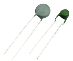
Lighting Switching PTC thermistor is ceramic PTC thermistor applied for lighting switching time delay, change hard start of the ballast and electronic energy-saving lamp to preheated start, extend fluorescent tube service life.
Lighting Switching PTC thermistor are used when a load in series with the PTC thermistor has to be switched off after a time delay and when switching occurs frequently.
A typical application of switching PTC thermistor is the preheating of electrode in energy-saving lamps or fluorescent lamps. Switching PTC thermistor can also be used as a power resistor for loading a capacitor, for example in power supplies or in control units of production equipment.

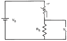
Typical configuration of a PTC thermistor for time delay
It’s applicable to various types of fluorescent lamp, electronic ballast and electronic energy-saving lamp. The PTC can be connected across the lamp resonator without changing the circuits. It can change hard start of the ballast and electronic energy-saving lamp to preheated start and the preheating time of the filament can come up to 0.4-2 seconds, which will extend the service life of the fluorescent tube by over 4 times.
Time Delay Circuit
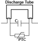
PTC Thermistor in discharge Tube circuit
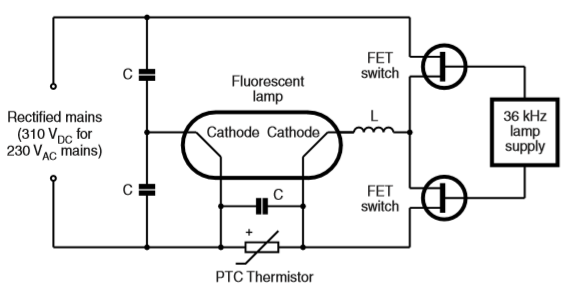
Typical electronic ballast circuit with PTC Thermistor
PTC thermistors Lighting Switching Application Circuit
The application of the PTC thermistor to achieve preheated start is as follows: Immediately after power is switched on, Rt is in normal temperature state and its resistance is far lower than the C2 resistance. The current through C1 and Rt forms a return circuit to preheat the filament. After about 0.4-2 seconds, Rt joule heat temperature exceeds Curie point Tsc and skips into high resistance state of far higher than C2 resistance. The current passes through C1 and C2 to form a return circuit, which causes L resonance and produces high voltage to light the fluorescent tube.
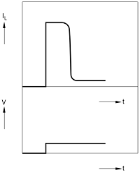
Typical delay of the load current
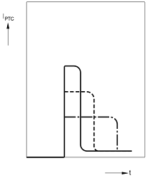
Typical switch-off behavior of a PTC thermistor
A typical application for switching PTC thermistor is the preheating of electrodes in energy-saving lamps or fluorescent lamps. Here the PTC thermistor is connected in series with the two electrodes of the lamp . When the rectified line is applied to the circuit the PTC thermistor is cold and low resistance. The lamp voltage is below the ignition voltage and the flowing current heats the electrodes and the PTC thermistor . After a certain period the PTC will switch, the voltage across the lamp will exceed the ignition voltage and the lamp will start to burn. Preheating of the electrodes lengthens the life of the lamp significantly. A full range of standard devices is available and custom engineered samples can be rapidly created for special lamp designs.
Switching PTC thermistor can also be used as a power resistor for loading capacitors, for example in power supplies or in control units of production equipment. Depending on the applied voltage and the capacitance of the capacitor, one or more
PTC thermistors in parallel will be necessary to load the capacitor. In contrast to fixed resistors, the PTC also offers protection against a possible shortcircuit in the capacitor.
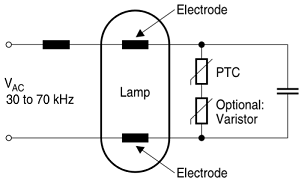
PTC electrode heating circuit
Principle circuit diagram for the preheating of electrodes in energy-saving lamps or fluorescent lamps.
The time needed for a PTC thermistor to switch from its low resistance state to a self-heated high resistance state may be used to provide for a time delay in a circuit. If a PTC thermistor is connected in parallel with a relay, the relay will only be energized after the time necessary for the PTC to switch from low to high resistance.
When a PTC is connected in series with a relay, the relay would energize immediately and would stay energized until the PTC heats up and increases in resistance. At that point, most of the voltage would be dropped across the PTC and the relay would no longer be energized.
The time for the PTC to switch in either case would be dependent upon the resistance and size of the PTC , as well as the ambient temperature and other circuit parameters such as supply voltage and other components in the circuit.
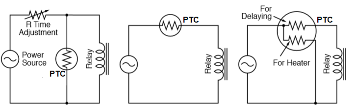
PTC Thermistor for relay delay operation

| Part Series | Dmax | Tmax | Φd | F |
| AMZ31-03 series | 4.5mm | 5.0mm | 0.5mm | 5.0mm |
| AMZ31-04 series | 5.5mm | 5.0mm | 0.6mm | 5.0mm |
| AMZ31-05 series | 6.5mm | 5.0mm | 0.6mm | 5.0mm |
| AMZ31-06 series | 7.5mm | 5.0mm | 0.5mm | 5.0mm |
| AMZ31-07 series | 8.0mm | 5.0mm | 0.6mm | 5.0mm |
| AMZ31-09 series | 10.0mm | 5.0mm | 0.6mm | 5.0mm |
| Part No. | Switching Temperature (C) |
Resistance at +25℃ (ohm) R25 |
Max. Voltage (VAC) |
Max. Current Imax (mA) |
|---|---|---|---|---|
| AMZ31-03 series | ||||
| AMZ31-03M151N500 | 80C | R25: 150 ohm±30% | 500V | 200mA |
| AMZ31-03M271N650 | 80C | R25:270 ohm ±30% | 650V | 200mA |
| AMZ31-03M391N650 | 75C | R25: 390 ohm ±30% | 650V | 200mA |
| AMZ31-03M681N800 | 75C | R25: 680 ohm ±30% | 800V | 200mA |
| AMZ31-03M102N800 | 75C | R25:1000 ohm ±30% | 800V | 100mA |
| AMZ31-03M152N800 | 70C | R25:1500 ohm ±30% | 800V | 100mA |
| AMZ31-03M222N800 | 70C | R25: 2200 ohm ±30% | 800V | 100mA |
| AMZ31-03M332N900 | 70C | R25: 3300 ohm ±30% | 900V | 100mA |
| AMZ31-03M472N900 | 70C | R25: 4700 ohm ±30% | 900V | 100mA |
| AMZ31-03N151N420 | 105C | R25:150 ohm ±30% | 420V | 200mA |
| AMZ31-03N175RN500 | 105C | R25:175 ohm ±30% | 500V | 200mA |
| AMZ31-03N225RN500 | 105C | R25:225 ohm ±30% | 500V | 200mA |
| AMZ31-03N271N500 | 105C | R25:270 ohm±30% | 500V | 200mA |
| AMZ31-03N301N650 | 105C | R25:300 ohm ±30% | 650V | 200mA |
| AMZ31-03N391N650 | 105C | R25:390 ohm ±30% | 650V | 200mA |
| AMZ31-03N561N650 | 105C | R25:560 ohm ±30% | 650V | 200mA |
| AMZ31-03N681N650 | 100C | R25:680 ohm±30% | 650V | 200mA |
| AMZ31-03N102N800 | 100C | R25:1000 ohm ±30% | 800V | 100mA |
| AMZ31-03N152N800 | 100C | R25:1500 ohm±30% | 800V | 100mA |
| AMZ31-03P151N420 | 115C | R25:150 ohm ±30% | 420V | 200mA |
| AMZ31-03P175RN420 | 115C | R25:175 ohm ±30% | 420V | 200mA |
| AMZ31-03P271N500 | 115C | R25: 270 ohm ±30% | 500V | 200mA |
| AMZ31-03P331N500 | 115C | R25: 330 ohm ±30% | 500V | 200mA |
| AMZ31-03P391N500 | 115C | R25: 390 ohm ±30% | 500V | 200mA |
| AMZ31-03P561N650 | 110C | R25: 560 ohm ±30% | 650V | 200mA |
| AMZ31-03P801N650 | 110C | R25: 800 ohm ±30% | 650V | 200mA |
| AMZ31-03P102N650 | 110C | R25: 1000 ohm ±30% | 650v | 100mA |
| AMZ31-04 series | ||||
| AMZ31-04M82RN500 | 80C | R25: 82 ohm±30% | 500V | 300mA |
| AMZ31-04M101N500 | 80C | R25: 100 ohm±30% | 500V | 300mA |
| AMZ31-04M151N500 | 80C | R25: 150 ohm±30% | 500V | 300mA |
| AMZ31-04M221N500 | 80C | R25: 220 ohm±30% | 500V | 300mA |
| AMZ31-04M391N650 | 75C | R25: 390 ohm±30% | 650V | 300mA |
| AMZ31-04M561N800 | 75C | R25: 560 ohm±30% | 800V | 200mA |
| AMZ31-04M681N800 | 75C | R25: 680 ohm±30% | 800V | 200mA |
| AMZ31-04M102N800 | 70C | R25: 1000 ohm±30% | 800V | 100mA |
| AMZ31-04M152N800 | 70C | R25: 1500 ohm±30% | 800V | 100mA |
| AMZ31-04M222N900 | 70C | R25: 2200 ohm±30% | 900V | 100mA |
| AMZ31-04M332N900 | 70C | R25: 3300 ohm±30% | 900V | 100mA |
| AMZ31-04N101N420 | 100C | R25: 100 ohm±30% | 420V | 300mA |
| AMZ31-04N151N500 | 100C | R25: 150 ohm±30% | 500V | 300mA |
| AMZ31-04N175RN500 | 100C | R25: 175 ohm±30% | 500V | 300mA |
| AMZ31-04N225RN500 | 100C | R25: 225 ohm±30% | 500V | 300mA |
| AMZ31-04N301N650 | 100C | R25: 300 ohm±30% | 650V | 300mA |
| AMZ31-04N391N650 | 100C | R25: 390 ohm±30% | 650V | 300mA |
| AMZ31-04N601N800 | 100C | R25: 600 ohm±30% | 800V | 200mA |
| AMZ31-04N851N800 | 100C | R25: 850 ohm±30% | 800V | 100mA |
| AMZ31-05 series | ||||
| AMZ31-05M101N500 | 80C | R25:100 ohm±30% | 500V | 400mA |
| AMZ31-05M151N650 | 80C | R25:150 ohm±30% | 650V | 400mA |
| AMZ31-05M271N650 | 80C | R25: 270 ohm ±30% | 650V | 400mA |
| AMZ31-05M391N800 | 75C | R25: 390 ohm ±30% | 800V | 400mA |
| AMZ31-05M561N800 | 75C | R25: 560 ohm ±30% | 800V | 300mA |
| AMZ31-05M102N900 | 70C | R25:1000 ohm ±30% | 900V | 100mA |
| AMZ31-05M152N900 | 70C | R25:1500 ohm ±30% | 900V | 100mA |
| AMZ31-05M222N900 | 70C | R25:2200 ohm ±30% | 900V | 100mA |
| AMZ31-05N101N500 | 100C | R25:100 ohm ± 30% | 500V | 400mA |
| AMZ31-05N151N650 | 100C | R25:150 ohm ± 30% | 650V | 400mA |
| AMZ31-05N221N650 | 100C | R25:220 ohm ± 30% | 650V | 400mA |
| AMZ31-05N301N800 | 100C | R25: 300 ohm ±30% | 800V | 400mA |
| AMZ31-05N391N800 | 100C | R25: 390 ohm ±30% | 800V | 400mA |
| AMZ31-05N561N800 | 100C | R25: 560 ohm ±30% | 800V | 300mA |
| AMZ31-05N681N900 | 100C | R25: 680 ohm ±30% | 900V | 200mA |
| AMZ31-05N851N900 | 100C | R25: 850 ohm ±30% | 900V | 100mA |
| AMZ31-05N102N900 | 100C | R25: 1000 ohm ±30% | 900V | 100mA |
| AMZ31-05P101N500 | 115C | R25:100 ohm ±30% | 500V | 400mA |
| AMZ31-05P151N500 | 115C | R25:150 ohm ±30% | 500V | 400mA |
| AMZ31-05P175RN650 | 115C | R25:175 ohm ±30% | 650V | 400mA |
| AMZ31-05P221N650 | 115C | R25:220 ohm ±30% | 650V | 400mA |
| AMZ31-05P301N650 | 115C | R25:300 ohm ±30% | 650V | 400mA |
| AMZ31-05P391N650 | 115C | R25:390 ohm ±30% | 650V | 400mA |
| AMZ31-05P561N800 | 110C | R25:560 ohm ±30% | 800V | 300mA |
| AMZ31-05P681N800 | 110C | R25:680 ohm ±30% | 800V | 200mA |
| AMZ31-05P102N800 | 110C | R25:1000 ohm ±30% | 800V | 100mA |
| AMZ31-06 Series | ||||
| AMZ31-06M101H650 | 80C | R25: 100 ohm ±25% | 650V | 600mA |
| AMZ31-06M121H650 | 80C | R25: 120 ohm ±25% | 650V | 600mA |
| AMZ31-06M151H800 | 80C | R25: 150 ohm ±25% | 800V | 600mA |
| AMZ31-06M201H900 | 80C | R25: 200 ohm ±25% | 900V | 600mA |
| AMZ31-07 Series | ||||
| AMZ31-07M70RN650 | 75C | R25: 70 ohm ±30% | 650V | 600mA |
| AMZ31-07M101N650 | 75C | R25: 100 ohm±30% | 650V | 600mA |
| AMZ31-07M151N650 | 75C | R25:150 ohm ±30% | 650V | 600mA |
| AMZ31-07M221N800 | 75C | R25: 220 ohm ±30% | 800V | 600mA |
| AMZ31-07M271N800 | 75C | R25: 270 ohm±30% | 800V | 600mA |
| AMZ31-07M391N800 | 75C | R25: 390 ohm ±30% | 800V | 400mA |
| AMZ31-07M561N900 | 75C | R25: 560 ohm±30% | 900V | 300mA |
| AMZ31-07M681N900 | 75C | R25: 680 ohm±30% | 900V | 200mA |
| AMZ31-07M102N900 | 75C | R25: 1000 ohm±30% | 900V | 100mA |
| AMZ31-07N70RN650 | 100C | R25: 70 ohm ±30% | 650V | 600mA |
| AMZ31-07N101N600 | 100C | R25:100 ohm ±30% | 600V | 600mA |
| AMZ31-07N151N650 | 100C | R25:150 ohm ±30% | 650V | 600mA |
| AMZ31-07N221N800 | 100C | R25:220 ohm ±30% | 800V | 600mA |
| AMZ31-07N271N800 | 100C | R25: 270 ohm ±30% | 800V | 600mA |
| AMZ31-07N331N800 | 100C | R25: 330 ohm ±30% | 800V | 400mA |
| AMZ31-07N391N800 | 100C | R25: 390 ohm ±30% | 800V | 400mA |
| AMZ31-07N561N900 | 100C | R25: 560 ohm ±30% | 900V | 300mA |
| AMZ31-09 series | ||||
| AMZ31-09M75RH900 | 80C | R25: 75 ohm ±25% | 900V | 1000mA |
| AMZ31-09M101H900 | 80C | R25: 100 ohm ±25% | 900V | 1000mA |
| AMZ31-09M151H1000 | 80C | R25: 150 ohm ±25% | 1000V | 1000mA |
| AMZ31-09M201H1000 | 80C | R25: 200 ohm ±25% | 1000V | 1000mA |
Reference Information for Selecting PTC Thermistor for Lighting Time Delay and Switching Preheated Starting Applications
1. The switching time Ts can be approximated as follows:
Ts=Cth .V.(TRef-TA)/P
TRef Reference temperature of PTC thermistor
TA Ambient temperature
Cth Heat capacity of PTC thermistor
V PTC thermistor volume
P Switch-on power of PTC thermistor
This shows that the switching time can be influenced by the size of the PTC thermistor , its reference temperature and the power supplied. Switching time are lengthened by increasing the volume or the reference temperature, high power consumption by the PTC thermistor , on the other hand, results in short switching time.
2. Single capacitor starting circuit has higher demand on PTC thermistor voltage withstanding capacity, general required withstanding voltage >800V.
3. PTC thermistor reliability can be increased through higher resistivity, higher resistivity PTC thermistor shall be chosen first at the premises of satisfying starting characteristics.
- Below 15W light , AMZ31-03, 04 series.
- 15-28W light, AMZ31-05, O6 series.
- 28-56W light, AMZ31-07 series.
- Around 60W light, AMZ31-09 series.
In the same dimension and the switching temperature, the lower the light watt, the higher the resistance at 25 centigrade (R25). The higher the R25, the higher the voltage withstanding capacity.
Content Headline
What Is Lighting Switching PTC Thermistor
Lighting Switching PTC Thermistor Application
Switching PTC Thermistor Operating Principle
Switching PTC Outlook and Dimension
AMWEI PTC Thermistor for Lighting Switching Data Sheet
Reference Information for Lighting Watts Corresponding to AMWEI PTC Thermistor Parts
Technical Information
PTC Thermistors Glossary and Definition
3 PTC Thermistors Characteristics, Resistance vs. Temperature RT Characteristic, Voltage vs. Current VI Characteristic, Current vs Time Characteristic.
PTC Thermistors Application Cautions for Soldering, Mounting, Cleaning.
PTC Thermistors Manufacturing and Quality Control.


