AMWEI Axial Leaded Glass Encapsulated DO35 Shape NTC Thermistor Temperature Sensor, 10K Ohm, Beta B(25/50): 3950K, Operating Temperature Range -40C to +250C.
AMWEI Product Code: NTC-AG-10KΩ-B3950-1%
AMWEI Axial Glass NTC Thermistor Sensor 10KΩ B3950 Appearance Dimension

Unit: mm
- NTC Thermistor chip hermetically sealed in DO35 glass shell.
- Tinned Dumet wire
Axial lead glass encapsulated NTC thermistor used for high temperature measurement, sensing, monitoring, detection and control. Typical application such as industrial process control, HVAC, oven, office equipment, etc.
- Resistance at 25C R25: 10K ohm+/-1%
- Beta Value B(25/50): 3950K+/-1%
- Optional R25 resistance tolerance, ±1%(F), ±2%(G), ±3%(H), or ±5%(J)
- Dissipation Factor: δ≥2mW/℃
- Thermal Time Constant (in still air): 12 seconds max.
- Rated Power: ≤50mW
- Insulation resistance: room temperature, 500VDC, 60 Seconds, ≥100MΩ.
- Operating temperature range: -40 to +250C.
| Temperature Centigrade |
Resistance (K Ohm) |
Temperature Centigrade |
Resistance (K Ohm ) |
Temperature Centigrade |
Resistance (K Ohm) |
|---|---|---|---|---|---|
| -40C | 285.900 KΩ | 80C | 1.256 KΩ | 200C | 0.070 KΩ |
| -35C | 210.375 KΩ | 85C | 1.072 KΩ | 205C | 0.064 KΩ |
| -30C | 157.411 KΩ | 90C | 0.918 KΩ | 210C | 0.058 KΩ |
| -25C | 119.121 KΩ | 95C | 0.789 KΩ | 215C | 0.053 KΩ |
| -20C | 90.852 KΩ | 100C | 0.681 KΩ | 220C | 0.049 KΩ |
| -15C | 69.687 KΩ | 105C | 0.588 KΩ | 225C | 0.045 KΩ |
| -10C | 53.700 KΩ | 110C | 0.511 KΩ | 230C | 0.041 KΩ |
| -5C | 41.555 KΩ | 115C | 0.445 KΩ | 235C | 0.038 KΩ |
| 0C | 32.298 KΩ | 120C | 0.389 KΩ | 240C | 0.035 KΩ |
| 5C | 25.283 KΩ | 125C | 0.341 KΩ | 245C | 0.032 KΩ |
| 10C | 19.884 KΩ | 130C | 0.300KΩ | 250C | 0.030 KΩ |
| 15C | 15.721 KΩ | 135C | 0.266KΩ | ||
| 20C | 12.501 KΩ | 140C | 0.235 KΩ | ||
| 25C | 10.000 KΩ | 145C | 0.209 KΩ | ||
| 30C | 8.049 KΩ | 150C | 0.187 KΩ | ||
| 35C | 6.518 KΩ | 155C | 0.167 KΩ | ||
| 40C | 5.311 KΩ | 160C | 0.150 KΩ | ||
| 45C | 4.353 KΩ | 165C | 0.135 KΩ | ||
| 50C | 3.588 KΩ | 170C | 0.122 KΩ | ||
| 55C | 2.975 KΩ | 175C | 0.111 KΩ | ||
| 60C | 2.479 KΩ | 180C | 0.101 KΩ | ||
| 65C | 2.077 KΩ | 185C | 0.092 KΩ | ||
| 70C | 1.748 KΩ | 190C | 0.084 KΩ | ||
| 75C | 1.479 KΩ | 195C | 0.076 KΩ |
| Test | Standard | Test Conditions and methods | Requirements |
|---|---|---|---|
| Soldering & Solderability | IEC60068-2-20 Test Ta |
Temperature: 230±5 ℃, 2-2.5mm away from ceramic body On: 2±0.5 Seconds. |
The terminations shall be evenly tinned |
| Resistant to soldering heat | IEC60068-2-20 Test Tb |
Temperature: 260±5℃, 2-2.5mm away from ceramic body On:10±1 Seconds. |
No visible damage, ΔR25/R25≤3% |
| Lead wire tensile | IEC60068-2-21 Test U |
Test Ua: Force 10N, On 10 Seconds; Test Ub: Bending 90C, Force 5N, Twice. |
No break off, ΔR25/R25≤3% |
| Test | Standard | Test Conditions | ΔR25/R25 (typical) | Remarks |
|---|---|---|---|---|
| Low temperature storage | IEC 60068-2-1 | Storage at low category temperature: -30 oC, Time: 1000 hours |
≤3% | No visible damage |
| Storage in dry heat | IEC 60068-2-2 | Storage at upper category temperature: 200 oC, Time: 1000 hours |
≤3% | No visible damage |
| Storage in damp heat, steady state (Humidity test) | IEC 60068-2-3 | Temperature: 40oC, Humidity:90%-95% RH, Duration:1000 hours |
≤3% | No visible damage |
| Temperature cycling | IEC 60068-2-14 | 1. -30C/30 minutes 2. 80C/5 minutes 3. 200C/30 minutes 4. 80C/5 minutes. Number of cycles: 5 Cycles |
≤3% | No visible damage |
Minimum lead wire length tailored to shall be ≥8mm.
In lead wire bending, bending point shall be more than 2mm away from glass body part.
Mounting and Handling Recommendations
Excessive forces applied to a sensor may cause serious damage. To avoid this, the following recommendations should be adhered to:
- No perpendicular forces must be applied to the body
- During bending, the leads must be supported
- Bending close to the body must be done very carefully
- Axial forces to the body can influence the accuracy of the sensor and should be avoided
- These sensors can be mounted on a minimum pitch of >5 mm
Soldering and Welding
- Avoid any force on the body or leads during, or just after, soldering.
- Do not correct the position of an already soldered sensor by pushing, pulling or twisting the body.
- Prevent fast cooling after soldering.
- For hand soldering, where mounting is not on a printed-circuit board, the soldering temperature should be <300C the soldering time <3 s and the distance between body and soldering point >1.5 mm.
- For hand soldering, dip, wave or other bath soldering, mounted on a printed-circuit board, the
- soldering temperature should be <300C, the soldering time <5 s and the distance between body and soldering point >1.5 mm.
- The distance between the body and the welding point should be >0.5 mm. Care should be taken to ensure that welding current never passes through the sensor.
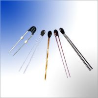
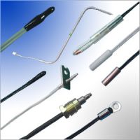
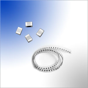
Other Related AMWEI NTC Thermistors Products for Temperature Sensing
Content Headline
Technical Knowledge
NTC Thermistor Glossary and Definition
How NTC thermistor beta value is calculated?
NTC Thermistor Manufacturing Process and Quality Control
Applications Articles
How to Select NTC Thermistor for Inrush Current Limiting?
NTC thermistor for temperature measurement and control selecting reference information.
Charging Control with AMWEI NTC thermistor
Reliable limiting of current surges by AMWEI NTC and PTC thermistor
How to Select Packaged Thermistor Temperature Sensor Probe Assembly ? 6 Steps


