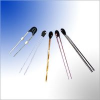
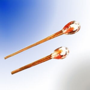
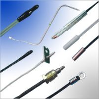
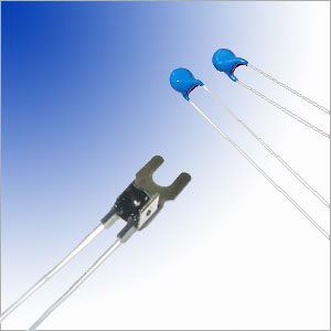
Silicon PTC Thermistor Temperature Sensor, Axial Leaded Glass Encapsulated DO35 Package, Resistance @25C 2000-2040Ω, Operating Temperature Range -55C–+150C, Cross NXP KTY81-222 Silistor.
AMWEI Product Code: AM-LPTC2000+2%
Unit: mm
- Silicon chip hermetically sealed in DO35 glass shell.
- Tinned Dumet wire
Silicon Sensor 2K RT Curve Temperature (Centigrade C)
- High accuracy and reliability
- Long-term stability
- Positive temperature coefficient;
fail-safe behavior - Virtually linear characteristics
- Motion control temperature sensor, temperature sensing and controls in drives and motors, spindles, inverters and control systems, etc.
- Industrial automation control equipment.
- Precision circuit and crystal oscillator temperature compensation.
- Temperature compensation of silicon semiconducting devices.
- Temperature compensation of instrumentation amplifier.
- A/D converter temperature compensation.
- Micro motor timing control.
- Automobile temperature detection and control.
- Medical equipment temperature detection and control.
- Linear PTC thermistors applications also include transmission, engine oil and coolant, heating system, overheating protection, amplifiers, power supplies, transducers, telemetry, computers, magnetic amplifiers, thermometry, meteorology, temperature regulation and over-temperature protection.
Resistance at 25C: 2000–2040Ω
Dissipation Factor:1.5mW/C min. in still air
Thermal Time Constant: 21 seconds max. in still air
Insulation Resistance: 100MΩ (DC=100V)
Maximum operating current: 8mA max.
Rated operating current 2mA
Rated Power: 50mW max.
Temperature measurement range: -55C~+150C
Storage time 2 Years (Room temperature, relative humidity <60%)
| Ambient Temperature | Temperature coefficient (%/K) |
Resistance (Ohm) |
|
|---|---|---|---|
| (°C) | (°F) | ||
| -55 | -67 | 0.99 | 990 |
| -50 | -58 | 0.98 | 1040 |
| -40 | -40 | 0.96 | 1146 |
| -30 | -22 | 0.93 | 1260 |
| -20 | -4 | 0.91 | 1381 |
| -10 | 14 | 0.88 | 1510 |
| 0 | 32 | 0.85 | 1646 |
| 10 | 50 | 0.83 | 1790 |
| 20 | 68 | 0.80 | 1941 |
| 25 | 77 | 0.79 | 2020 |
| 30 | 86 | 0.78 | 2100 |
| 40 | 104 | 0.75 | 2267 |
| 50 | 122 | 0.73 | 2441 |
| 60 | 140 | 0.71 | 2623 |
| 70 | 158 | 0.69 | 2812 |
| 80 | 176 | 0.67 | 3009 |
| 90 | 194 | 0.65 | 3214 |
| 100 | 212 | 0.63 | 3426 |
| 110 | 230 | 0.59 | 3643 |
| 120 | 248 | 0.53 | 3855 |
| 130 | 266 | 0.44 | 4048 |
| 140 | 284 | 0.33 | 4208 |
| 150 | 302 | 0.20 | 4323 |
Minimum lead wire length tailored to shall be ≥8mm.
In lead wire bending, bending point shall be more than 2mm away from glass body part.
Mounting and Handling Recommendations
Excessive forces applied to a sensor may cause serious damage. To avoid this, the following recommendations should be adhered to:
- No perpendicular forces must be applied to the body
- During bending, the leads must be supported
- Bending close to the body must be done very carefully
- Axial forces to the body can influence the accuracy of the sensor and should be avoided
- These sensors can be mounted on a minimum pitch of >5 mm
Soldering and Welding
- Avoid any force on the body or leads during, or just after, soldering.
- Do not correct the position of an already soldered sensor by pushing, pulling or twisting the body.
- Prevent fast cooling after soldering.
- For hand soldering, where mounting is not on a printed-circuit board, the soldering temperature should be <300C the soldering time <3 s and the distance between body and soldering point >1.5 mm.
- For hand soldering, dip, wave or other bath soldering, mounted on a printed-circuit board, the
- soldering temperature should be <300C, the soldering time <5 s and the distance between body and soldering point >1.5 mm.
- The distance between the body and the welding point should be >0.5 mm. Care should be taken to ensure that welding current never passes through the sensor.


