PTC Heater Chips Disks, Honeycomb Heater

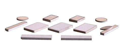
PTC Thermistor Heater Chips

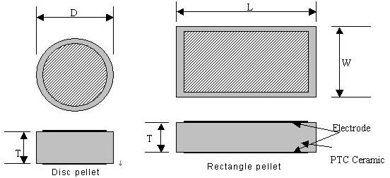
PTC Thermistor Heater Chips Disc Rectangle Structure
PTC thermistor heater chips surface temperature: 50-320C
Operating voltage 6 V -480V
Resistance @ 25C (R25) :1-5000Ω
Dimensions:
In Disk round diameter: 5~25mm
In Rectangle form: Length: 5~40mm: Width: 3-20mm
Some AMWEI PTC Heater Chips Products Examples
- PTC Thermistors Heater Disk 220V 270C Diameter 20mm R25 2K-10K Ohm
- PTC Heater Disk 12V 130C 9 Ohm Diameter 13mm
- PTC Heater Disk 230V 200C 8X3mm
- PTC Heater Rectangular 230V 160C 1k ohm 35X6X2.54mm
- PTC Heater Rectangular 230V 125C 1k ohm 35X6X2.54mm
- PTC Ceramic Thermistor Heater 110V 220V 260C 24x15X2.5mm Rectangular Clamp Contact
- PTC Heater Ring 220V 110C Diameter Diameter Outer 14.5mm, Inner 4.3mm R25: 100-1000 Ohm
Honeycomb heaters are small PTC discs that are pierced by many holes, the holes in each disc allow the airflow across the disc to be heated.
In wind blown state, Honeycomb heaters can produce constant temperature hot air, widely applied in warm air request condition. No glowing parts, versatile voltage rating, stable powerwatt.

Honeycomb PTC Heaters
In selecting a PTC thermistor heater, the following factors should be considered
- Thermal Connections
- Switch Temperature (Ts, also called Curie Temperature, Reference temperature)
- Resistance at 25 °C (R 25)
- Surface Area
- Maximum Voltage (Vmax)
Ceramic PTC heaters are usually most efficient when they are flat and thin and have a smooth surface finish. For a PTC thermistor to operate as a heater, it must have a way to dissipate its heat to the medium, either by convection (air or liquid flow) or conduction. One common method is to use a spring contact as both the electrical and mechanical connection . One advantage of this clamping technique is that it allows stress-free thermal expansion. Other techniques involve using electrically conductive epoxies or solder joints to connect the PTC to the heat spreader.
The switch temperature is very important because, in most heater applications, the maximum PTC surface temperature is just a few degrees higher its switch temperature. Thus, the maximum temperature of the medium to be heated is directly related to the switch temperature Ts of the PTC.
The R25 of the PTC heater should not be so low that it causes inrush current problems, but not so high that there is not enough power available to heat the PTC to its switched condition. The PTC cold resistance will, however, influence the heat-up rate of the medium since a lower resistance allows for higher initial I2R heating.
The surface area of the PTC heater influences the heat-up and cool-down rates of the medium as well as the power dissipated. Multiple PTCs are often used in heater design to obtain the desired results. As with any PTC thermistor application, the heater design should not exceed the maximum recommended voltage ratings.
Operating voltage
This is usually between 12 and 480 V.
Surface temperature Tsurf
Surface temperature Tsurf varies from 40 to 300 °C.
The higher the surface temperature selected, the greater the power that can be dissipated. A high surface temperature leads to considerable thermal stress on the entire design if thermal dissipation is poor.
Dimensions
PTC thermistor are available in circular and rectangular designs. The surface area of the PTC thermistor depends on the heat output required. Its thickness depends on the operating voltage used in the application.
A thickness of 1.4 mm is recommended for 12 V applications, 2.0 to 3.2 mm for 230 V applications. The thicker the thermistors, the lower the field strength at the components and thus the more reliable the application, e.g. in handling voltage peaks in the line.
Resistance
As the resistance of PTC thermistor varies with voltage, the resistance Rmin at the rated voltage is given. This defines the maximum current flowing as the
thermistor heats up: Iin = V / Rmin. Iin determines the heating characteristics of the PTC thermistor . Rmin varies from 1 Ω to several kΩ, depending on design.
If the heating output of one heating PTC thermistor is not sufficient for a certain application, several PTCs can be mounted together, i.e. if the thermistors are electrically connected in parallel. In this way output power up to 2 kW may be achieved in a compact design.
Content Headline
PTC Thermistor Heater Chips in Disk Rectangle Arc Shape
Honeycomb PTC Heaters
Consideration Factors in Designing PTC thermistors as Heater
Selection criteria for PTC heating thermistors
PTC Heater Assembly
PTC Heaters with Wire, Single Solder, Silicon Coated, Insulated
Metal Housing PTC Conductive Heater
PTC Cartridge Heaters, Threaded Al, Metal Tube
Flow through PTC Liquid Water Heater
Build-in PTC Liquid Water Heater
PTC Air Heater
PTC Convection Heaters Anti-freeze Anti-damp
PTC Diesel Fuel Heater
Technical Information
PTC Thermistors Glossary and Definition, 3 PTC thermistors Characteristics, Resistance vs. Temperature RT Characteristic, Voltage vs. Current VI Characteristic, Current vs Time Characteristic.
PTC Thermistors Application Cautions for Soldering, Mounting, Cleaning.
PTC Thermistors Manufacturing and Quality Control
The Advantage of Using PTC Thermistor as Heating Elements and Application Precaution
Dimensioning PTC thermistors
